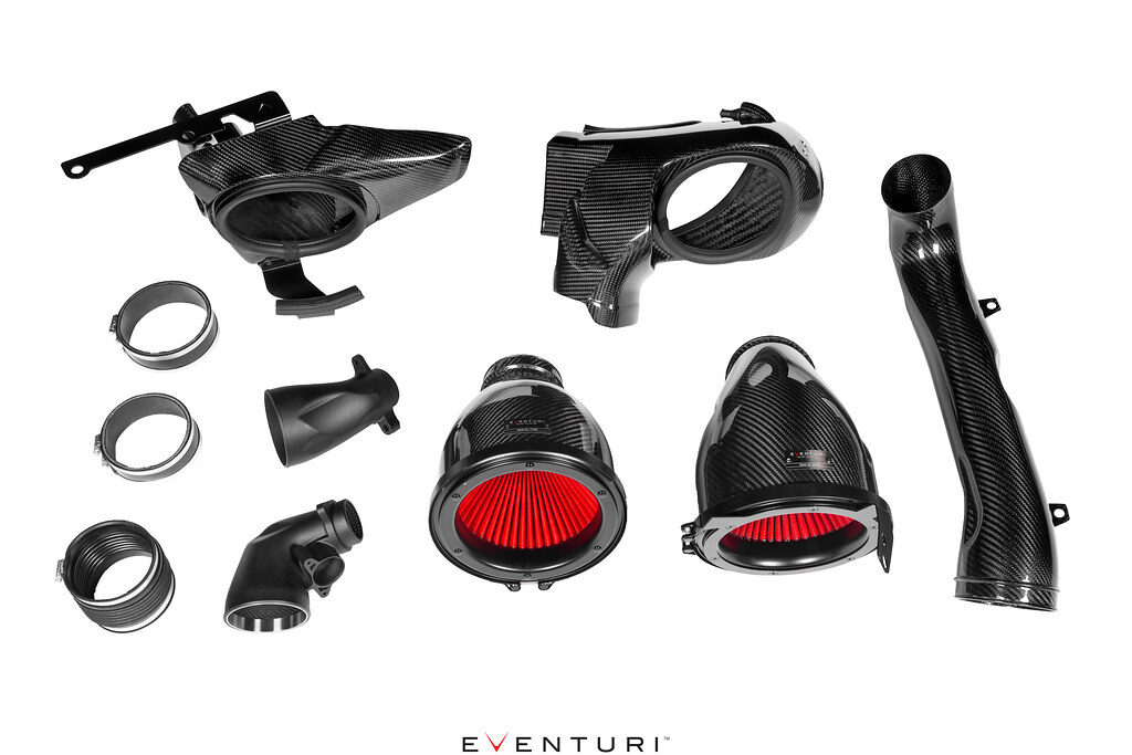
The #1 carbon fiber intake system for the G8X platform. M2/M3/M4
The best carbon fiber intake system for the BMW G8X M3 and M4 in 2026, no doubt. Lightweight, increased horsepower and insane cosmetics. What’s the cost? Weight savings? HP gains? See below. Bilal, Eventuri’s head of engineering has released a detailed deep dive video exploring the design and development of the G8X M2, M3, and M4 turbo inlets that are included with every Eventuri S58 intake system. His walkthrough provides a rare look into the airflow theory, packaging constraints, and performance targets that shaped the final production components. For enthusiasts who want to understand how and why these parts make a difference, it offers valuable insight into the level of engineering behind what appears to be a simple section of the intake path.
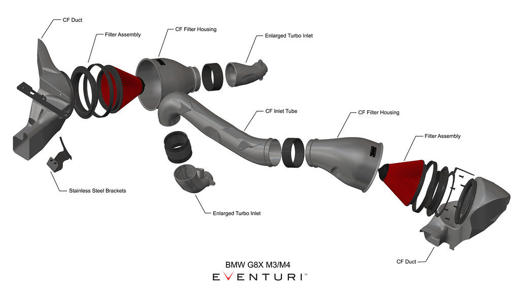
On the G8X platform, most performance conversations revolve around the components you can immediately see such as the intake system, exhaust, software, and turbochargers. Yet one of the most influential parts of the entire airflow path sits just before the compressor and rarely gets the attention it deserves. The turbo inlet plays a critical role in determining how efficiently the turbocharger operates, how quickly it responds, and how much power the system can ultimately support.
As power levels on the S58 continue to climb, the importance of this section of the intake tract becomes increasingly clear. The inlet is the final pathway the air travels before reaching the turbocharger. Any disruption here forces the turbo to work harder to achieve the same result, increasing thermal load and reducing overall efficiency.
We’ve included the video below and highly recommend taking the time to watch it.
The Limitation in the Factory Inlet Path
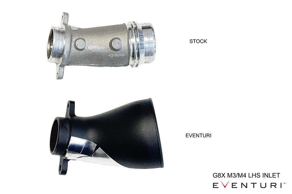
The OEM S58 inlet design is a product of mass production priorities. It must fit within tight packaging constraints, meet cost targets, and integrate seamlessly into a wide range of operating conditions. While it performs well for a stock vehicle, it introduces several compromises when airflow demand increases.
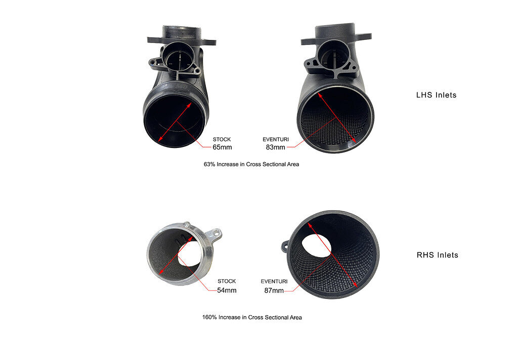
The factory geometry includes sharp directional changes, uneven internal transitions, and localized reductions in cross sectional area. These characteristics create turbulence and pressure loss just before the compressor. Instead of delivering a clean, stable column of air, the turbocharger receives airflow that has already lost energy.
That loss has a measurable effect. The turbocharger must operate at a higher shaft speed to reach the same boost target, which increases heat and reduces the efficiency window in which it performs best.


Boundary Layer Control and the Internal Dimple Design
One of the most overlooked details in the Eventuri S58 turbo inlet design is the use of a textured internal surface in specific areas of the flow path. Rather than leaving the entire inlet wall completely smooth, the inlets incorporate a series of dimples that are strategically positioned to manage the boundary layer as airflow approaches the turbocharger.
As air moves through an intake tract, a thin layer of slower moving air forms along the inner wall. This is known as the boundary layer. In areas where the airflow is forced to change direction or expand, that slow moving layer can separate from the surface. When separation occurs, turbulence increases, effective flow area is reduced, and pressure losses rise.
The dimple pattern is used to keep that boundary layer attached to the wall.
By energizing the thin layer of slower moving air near the surface, the dimples help the main airflow column remain stable through transitions in the inlet geometry. This reduces flow separation in critical zones and allows the turbocharger to receive a more uniform and higher energy air stream.
The result is not about increasing a single peak flow number. It is about maintaining airflow quality as mass flow demand rises.
- More consistent airflow into the compressor
- Reduced localized turbulence before the turbo
- Improved efficiency at higher load and boost levels


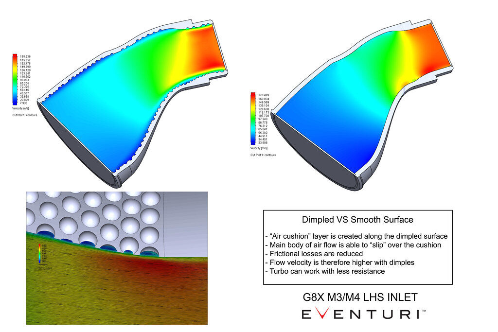
This type of surface treatment is commonly seen in aerospace and high level motorsport applications where managing airflow attachment is more important than simply enlarging a passage. In the context of the S58, it is another example of designing for real operating conditions rather than chasing a maximum flow figure.
This boundary layer strategy is supported by published fluid-dynamics research on dimpled internal flow surfaces. Studies show that controlled surface texturing increases momentum exchange close to the wall and alters the local flow structure compared to a smooth passage. In practical terms, this helps the airflow remain attached through transitions and delivers a more uniform, higher-energy air stream to the compressor.
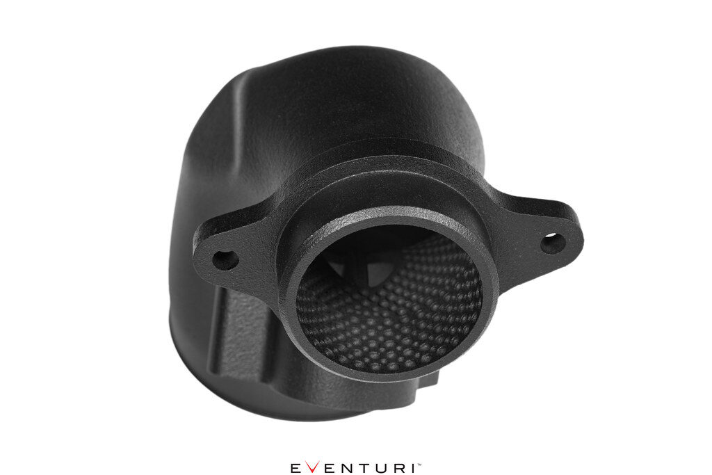
Manufacturing Method and Why 3D Printing Was Required
The internal dimple structure is not a styling feature and it cannot be produced using conventional manufacturing methods. The geometry exists inside a fully enclosed and continuously changing inlet path, which means traditional molding or machined construction would not be able to create the required surface detail with the necessary precision.
Additive manufacturing was the only viable solution.
By using a high temperature 3D printed construction, Eventuri was able to form the inlet as a single piece with the dimples integrated directly into the internal wall. This allows the boundary layer control strategy to function exactly as designed without seams, bonded sections, or secondary inserts that could disrupt airflow.
Just as important, the process makes it possible to maintain the exact internal shape that was developed in CAD and validated through testing. The airflow path, the cross sectional transitions, and the surface texture are all produced as one continuous structure, ensuring that the performance seen in development is what the end user receives on the car.
In this case, 3D printing is not simply a modern manufacturing choice. It is the enabling technology that allows the aerodynamic features inside the inlet to exist at all.
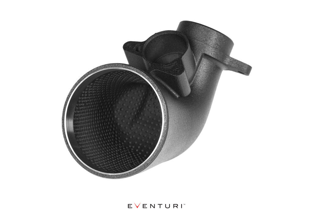
Integration and Fitment
Efficiency is only valuable if it can be achieved without compromising reliability or serviceability. The inlet must fit within the factory environment, maintain correct sensor relationships, and clear surrounding components under all operating conditions.
A direct bolt on design ensures that the improved airflow path integrates with the vehicle as if it were an original component.
The Missing Link in the S58 Airflow System
By improving the final section of the intake path before the compressor, the entire system operates under better conditions. The turbocharger works less for the same result. Temperatures remain more stable. Response improves. Power becomes more repeatable.
What This Means for Turbocharger Operation
Improving the efficiency of the inlet path changes how the turbocharger behaves across the entire rev range.
- Boost builds more progressively
- Transient response improves
- The mid range becomes more immediate
- The turbo operates in a more efficient zone
Designed for the Way the Platform Is Used
From daily driven cars to high output builds, the S58 continues to push into higher performance territory. Supporting that progression requires components that are engineered with efficiency, thermal control, and airflow stability in mind.
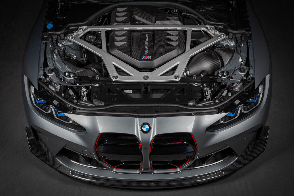
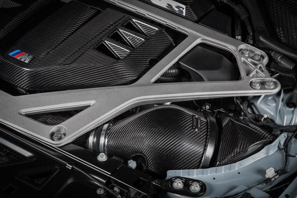
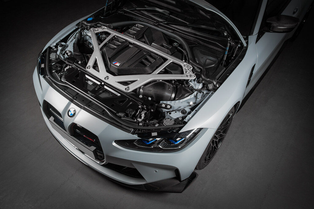
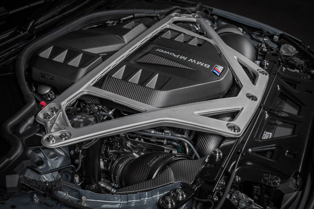
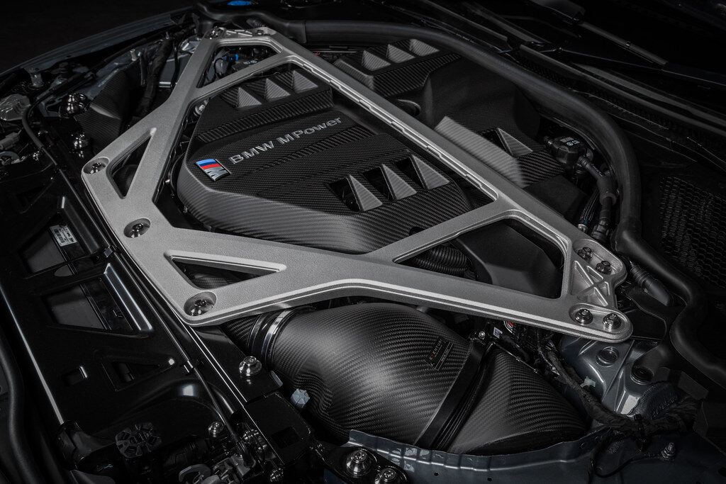
Installed photos of the complete intake system. Beyond the extensive year long research and development and technical validation behind its performance, it also stands out as one of the best looking and best sounding intake solutions available for the S58 platform.